Design of AND gate aggregation
Regarding to the AND gate linker, as shown in Fig.1, there are two kinds of linker, one kind of linker has complementary array to one beads(D1 in figure) in one of its edge, and the other side of edge is complementary to the other kind of linker’s one edge, whose array’s the other side is complementary to the other beads(D2)’s strand. The two kinds of linker strands are amplified from complementary strands in same way to the single linker, and two linker make cohesion in character T-shape, and both of the horizontal edge of capital T make cohesions to two kinds of beads. Thus, only in the case of both two kinds of linker exists, beads gather together and strength of fluorescence grows according to the amount of double stranded DNA.
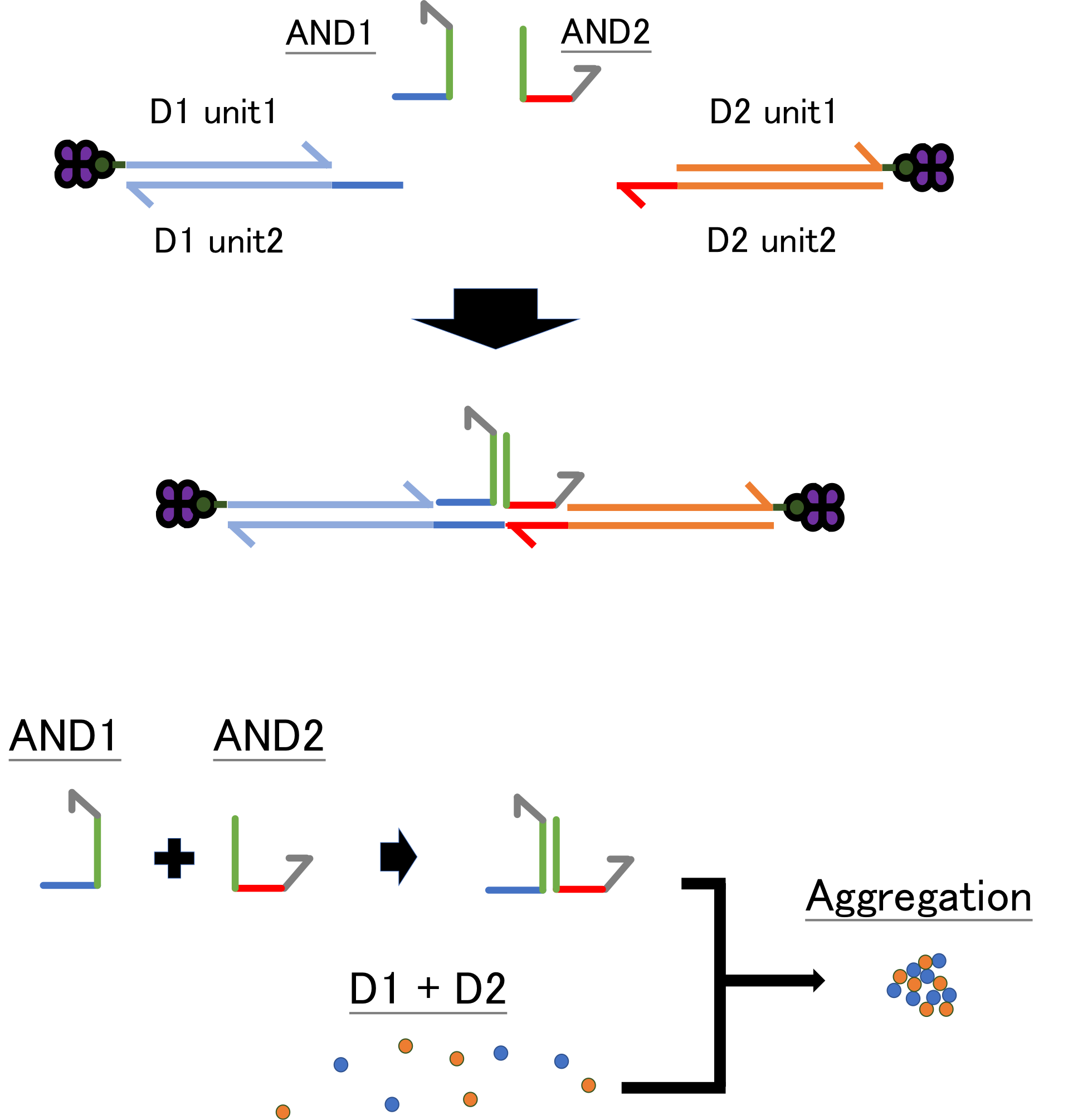
Fig.1 Design of logic gate aggregation (AND gate)
Experiment AND1: Aggregation of Beads with AND gate linker
Object: Check the activity of AND gate linker
We tested whether the combination of two types of DNA linker work as AND logic gate.
Method
We designed AND 1 linker and AND 2 linker, which bond complementarily. Then, we prepared 4 different solutions (AND 1, AND 2, AND 1 + AND 2, control), and added them to the solution which beads D1 and D2 were in. We incubated each solution at room temperature for 10 hours and observed them with a microscope.
Result and Discussion
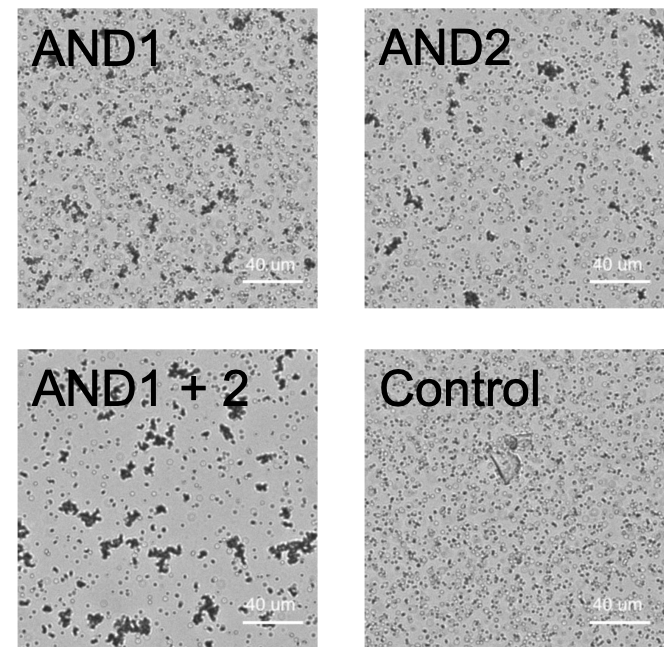
Fig.2 Microscopic images of each solution after incubation for ten hours. Scale bar= 40 µm.
We found that the beads aggregated when we put AND 1 and AND 2 together. The beads aggregations were partially observed in the conditions of only AND 1 or only AND 2 condition. The aggregation was not observed in control condition. Therefore, AND gate linker functioned as programmed.
Experiment AND2: Amplification of AND gate linker
Object: Check the amplification of AND gate linker and the bonding of the linkers
We checked the amplification of two kinds of AND gate linker caused by input strand in our experimental system, and the bonding of AND gate linkers.
Method
We designed two kind of DNA strands (α strand, β strand) so that we could amplify normal linker from each input DNA strands (α to linker AND 1, β to linker AND 2). Then we prepared 4 kinds of samples. (α 1 nM, β 1 nM, α 1 nM + β 1nM, control). We traced the amount of fluorescence which showed the bonding of DNA with a thermal cycler (in the 45 ℃ incubation condition).
Result and Discussion
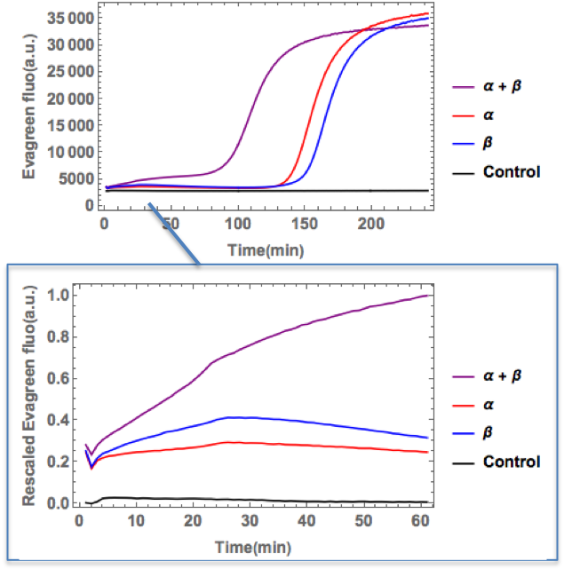
Fig.3 The time transition of fluoresence intensity of each sample after incubation in thermal cycler. The enlarged view is also shown in the lower part of this figure.
The amount of fluorescence was clearly increased in α strand + β strand solutions compared with ones in only α strand or β strand solutions. In control solution few fluorescence was detected. Therefore, PEN DNA toolbox was correctly functioned about two strands, so strand α was conversed to linker AND 1, strand β was conversed to linker AND 2. Furthermore, created two linkers (linker AND 1, linker AND 2) bonded complementary.
Experiment OR: Amplification of strand α and normal linker and Aggregation of Beads with normal linker
Object: Find the appropriate concentration of α to linker in OR gate experiment
Method
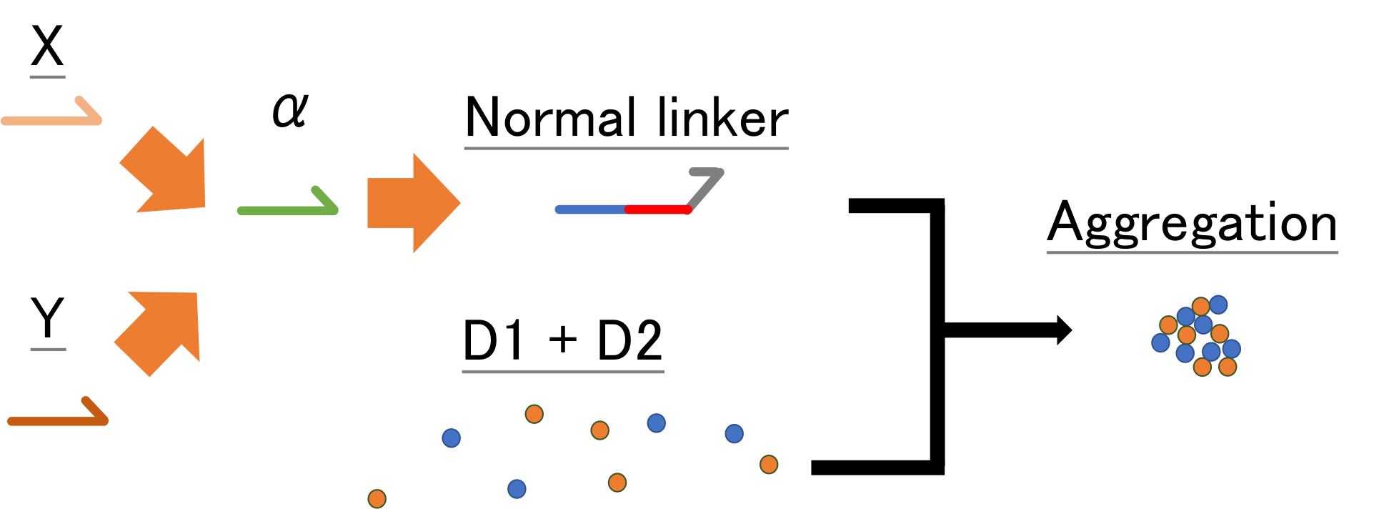
We added Strand X (2 nM) to the 4 kinds of solution which templates (each condition; X to α, α to linker, α to α) and beads D1, D2 were in, and put the system in lanes of chamber. We incubated each solution at 45 degrees and traces them with a microscope.
Result and Discussion
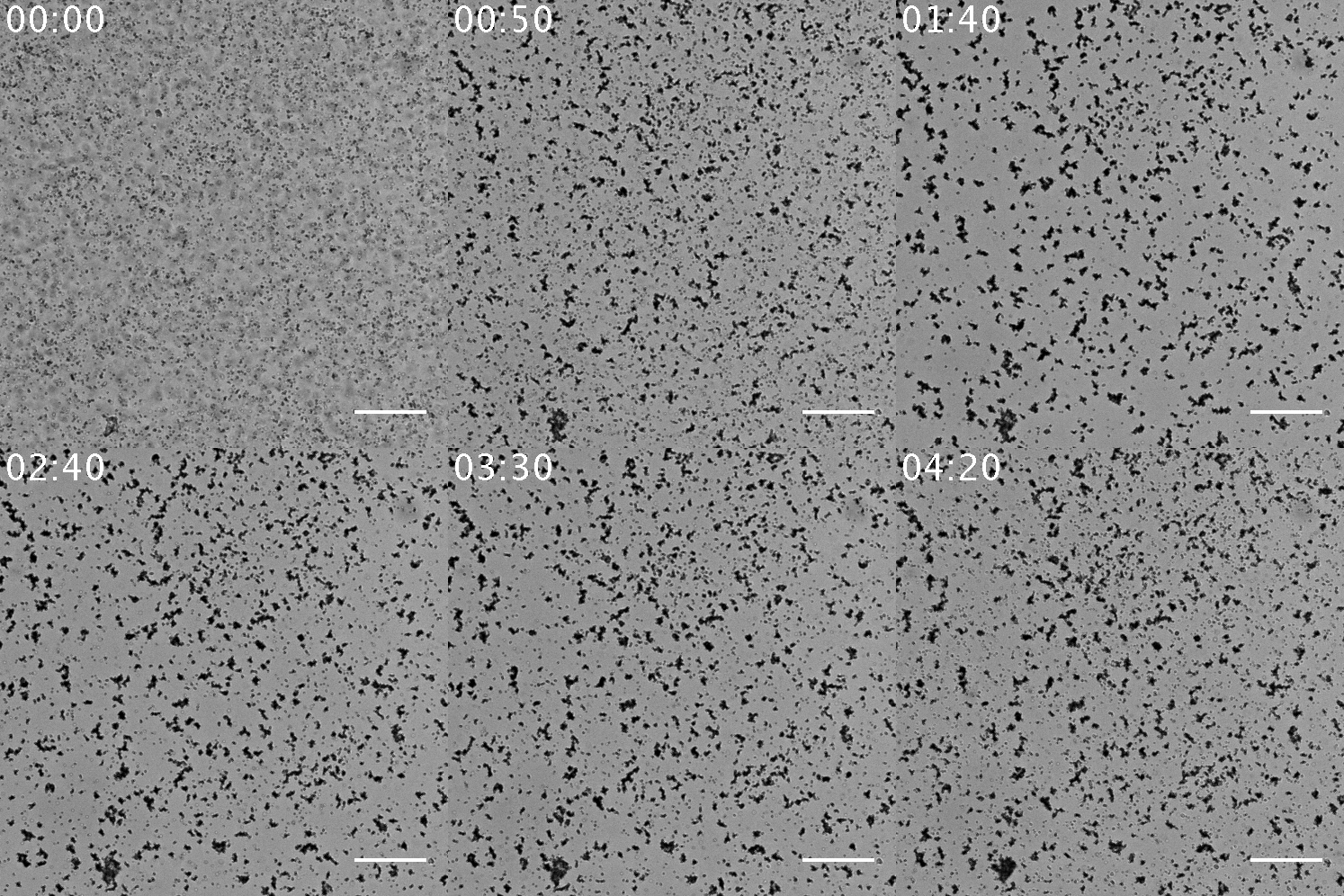
Fig.5 The video of the aggregation of beads seen in the sample with 10 nM α to linker. The scale bar= 80 µm.

Fig.6 Microscopic images of each solution after incubation. Scale bar= 80 µm.
When using 10 nM template α to linker, this series of systems works and beads aggregated, but there is little aggregations when using the other concentration of template α to linker. It is found that in 100 nM, 10 nM, 1 nM and 0 nM of template α to linker, 10 nM of is the most appropriate concentration. In regard to 100 nM, too much template α to linker inhibits the amplification of α by template α to α, so template α to linker does not work well. In regard to 1 nM, too little template α to linker does not produce linker much. Note that as little as 1 nM of X strand can be amplified and observed visibly in the form of aggregation.
Protocol
Experiment AND1: Aggregation of Beads with AND gate linker
Mastermix is as same as Experiment 1.
| Sample1 | Mastermix + Linker AND1 10uM |
|---|---|
| Sample2 | Mastermix + Linker AND2 10uM |
| Sample3 | Mastermix + Linker AND1 10uM + Linker AND2 10uM |
| Sample4 | Mastermix + MQ |
| Mastermix | |
|---|---|
| Ppmix | 25% |
| α to linker AND1 | 100nM |
| β to linker AND2 | 100nM |
| D1 unit2 | 100nM |
| D2 unit2 | 100nM |
| Evagreen | 5% |
| BSA9000S | 1% |
| BstWS2.0/10 | 3% |
| NB.BsmI | 4% |
| RecJtt/140 | 1% |
| MQ | full up |
| Sample1 | Mastermix + α1nM β1nM |
|---|---|
| Sample2 | Mastermix + α1nM |
| Sample3 | Mastermix + β1nM |
| Sample4 | Mastermix + MQ |
| 100 nM | 10 nM | 1 nM | NC | |
|---|---|---|---|---|
| TE Buffer | 1.7 | 1.7 | 1.7 | 3.7 |
| PPmix-dNTP | 5 | 5 | 5 | 5 |
| dNTP | 0.8 | 0.8 | 0.8 | 0.8 |
| D1 | 2 | 2 | 2 | 2 |
| D2 | 2 | 2 | 2 | 2 |
| EvaGreen | 1 | 1 | 1 | 1 |
| Template Mix 'OR' | 2 | 2 | 2 | 2 |
| α to linker | 2 (100 nM) | 2 (10 nM) | 2 (1 nM) | 0 |
| BSA | 0.2 | 0.2 | 0.2 | 0.2 |
| Bst | 0.3 | 0.3 | 0.3 | 0.3 |
| Nb.BsmI | 0.8 | 0.8 | 0.8 | 0.8 |
| RECJtt | 0.2 | 0.2 | 0.2 | 0.2 |
| 20 nM X | 1 | 1 | 1 | 1 |
| 20 nM Y | 1 | 1 | 1 | 1 |
| Total | 20 | 20 | 20 | 20 |
| Template Mix 'OR' | |
|---|---|
| 1 µM α to α | 30% |
| 1 µM α drain | 15% |
| 1 µM X to α | 1% |
| 1 µM Y to α | 1% |
| TE Buffer | 53% |
Materials (regarding logic gate experiments)
| Target | |
|---|---|
| X | TAGCTTATCAGACTGATGTTGA |
| Y | AGGCAAGATGCTGGCATAGCTGT |
| X to α | C*G*A*TCCTGAATG CAA TCAACATCAGTCTGAT |
| Y to α | C*G*A*TCCTGAATG CAA ACAGCTATGCCAGCA |
| Y to β | C*A*G*TCCAGAATG CAA ACAGCTATGCCAGCA |
| AND gate | |
|---|---|
| Linker AND 1 | CATTC GACG AA AAGGGG GAATG |
| Linker AND 2 | CATTC CCCCTT AA GGATGC GATGT |
| α to Linker AND 1 | CATTC CCCCTT TT CGTA GAATG CGATCCTGAATG |
| β to Linker AND 2 | ACATCGCATCC TT AAGGGG GAATG CGATCCTGAATG |
| β | CATTCTGGACTG |
|---|---|
| β to β | CAGTCCAGAATG CAGTCCAGAA |
| drain β | T*T*T*TT CAGTCCAGAATG |
| β to drain α | C*A*T*TCAGGATCG TTCAATGACT CAGTCCAGAA |